 Home
Home
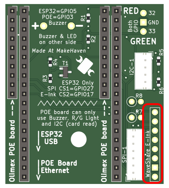
It is commonly helpful to have a small, dedicated device to read a member's RFID badge. This board can be mounted under an ESP32 DevKitC Boards, Olimex-POE or an Olimex-POE-ISO board.
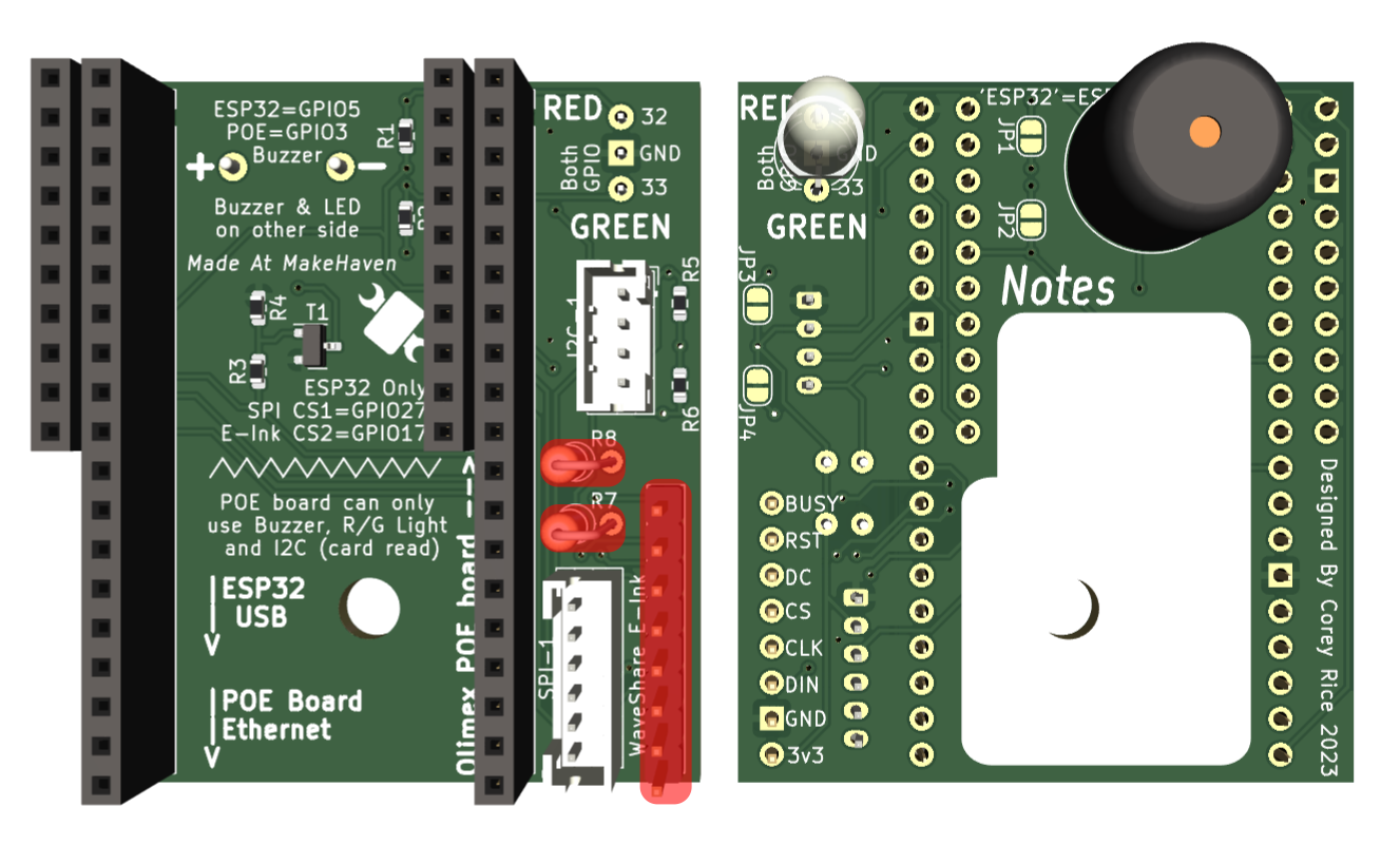
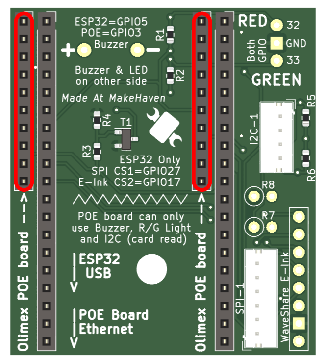
The design shown above allows the easy connection of a few types of microcontrollers to common devices. These can be used for card-readers of E-Ink displays among other things.
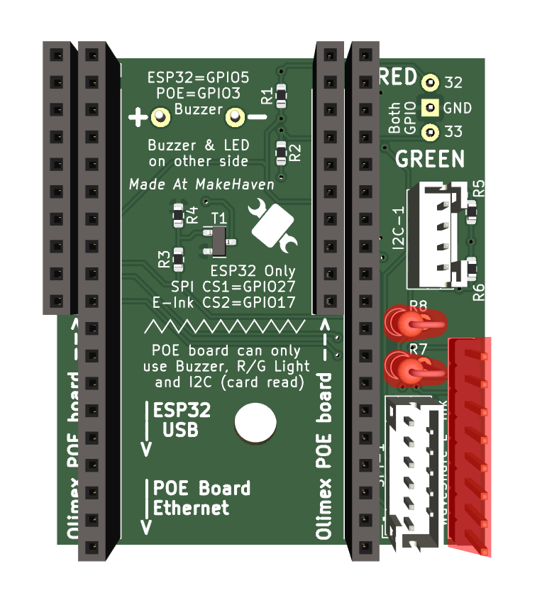
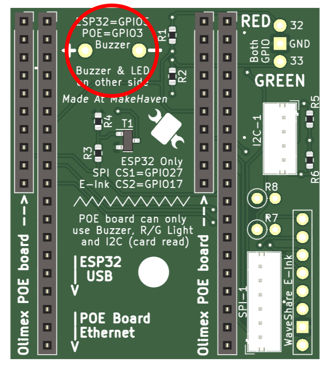
The red-covered components are shown, but not included in the most recent production-run of the board: It is commonly convenient to solder these components in later, as you may want them configured differently for different applications. For example, although shown on the top here, the buzzer will often be placed on the bottom of the board to direct the noise outward.
The gerber Files for this design are here, and the BOM and position files are formatted for ordering from JLCPCB.
The following are links to downloadable Fusion 360 models for these reader-holders.
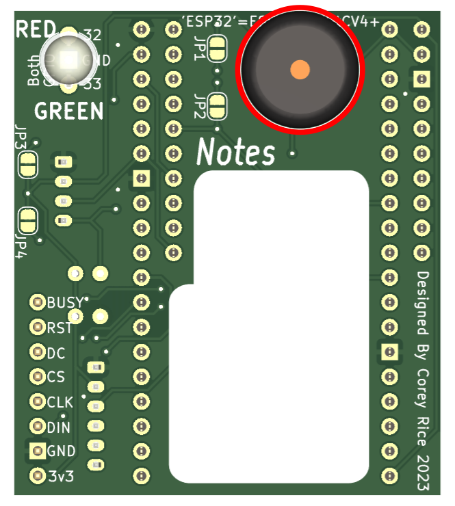
Here is a rendered example of the first of these designs:
There are a handful of places to interact with this board. They are explained below.
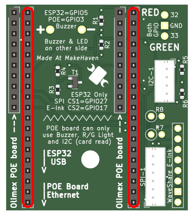
There are two possible Microcontrollers designed to interface with this board, each in their own set of headers.
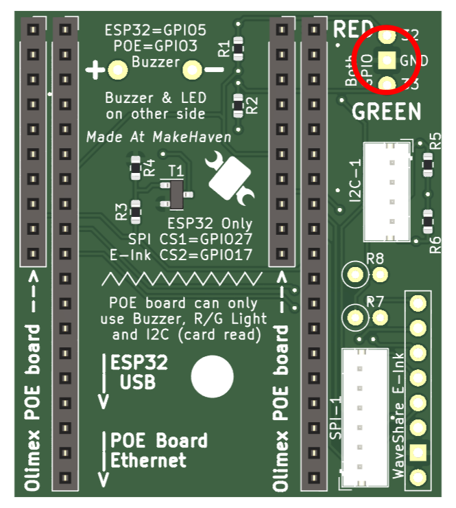
First is the ESP32-DevKitC-V4+ group of boards that are commonly available for sale online. These boards fit into the longer (19 pin) pair of headers.
Second is the Olimex ESP32-POE or the Olimex ESP32-POE-ISO boards. These both fit on the 10-pin headers.
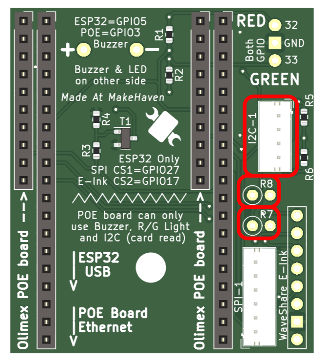
For this project, this is where the card reader will connect.I2C communication is generally helpful for most types of chip-to-chip communication.
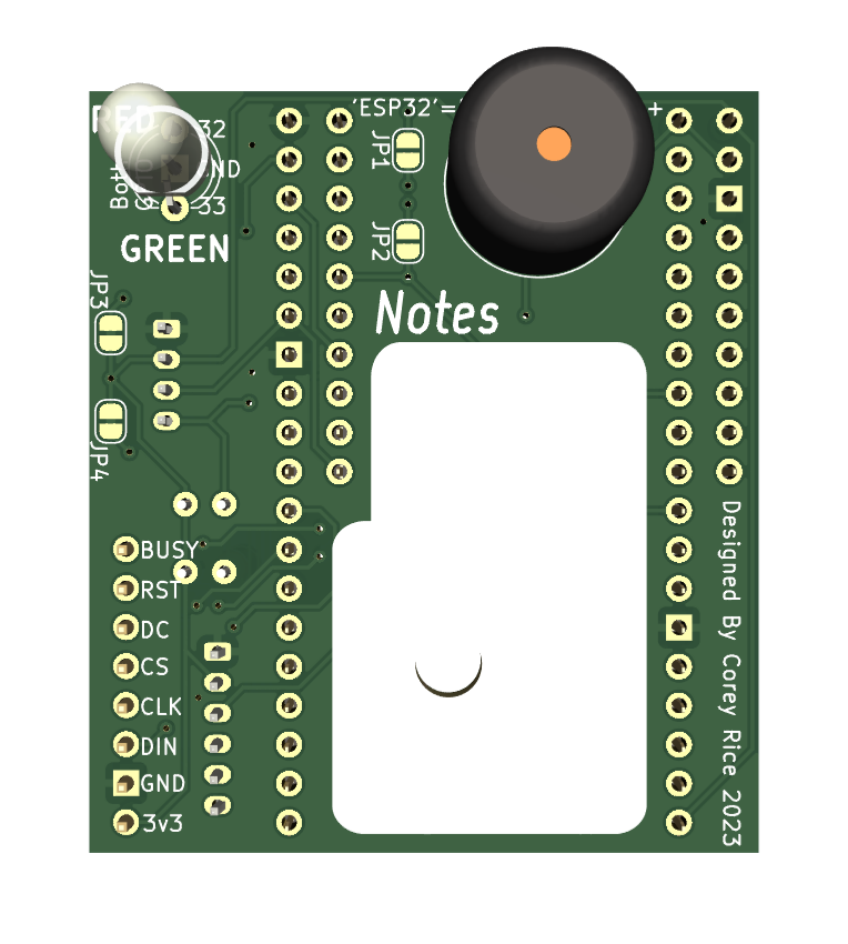
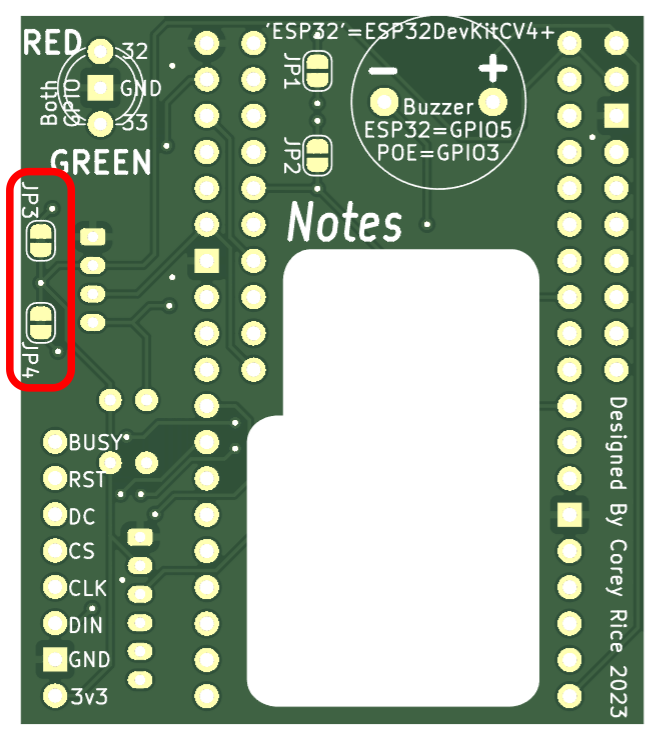
On the front, there is the JST connector, and two open spots where you could add resisitors. On the back of the baord there are two already-connected jumpers. These resistors and spaces for more are all in place because of the need for I2C communication to have pull-up resistors. The default state is to use the pull-up resistors on the microcontroller. If you need more resistance (because of spotty communication) you can cut the trace between the pads on JP3 and JP4 to add in the 2.2k resistors that are already soldered in parallel to the jumpers. IF you find that this still doesn't solve your communication problems, then you can solder in whatever resistors work of your application in the open spaces for R7 and R8. Hopefully, all these pull-up resistors will not be needed, and you can leave the setup as-is.
From experience, we have found that the ESP32-DevKitC-V4 requires the two jumpers on the back to be cut: JP3 and JP4. The same is (probably) not true of the Olimex-POE boards.
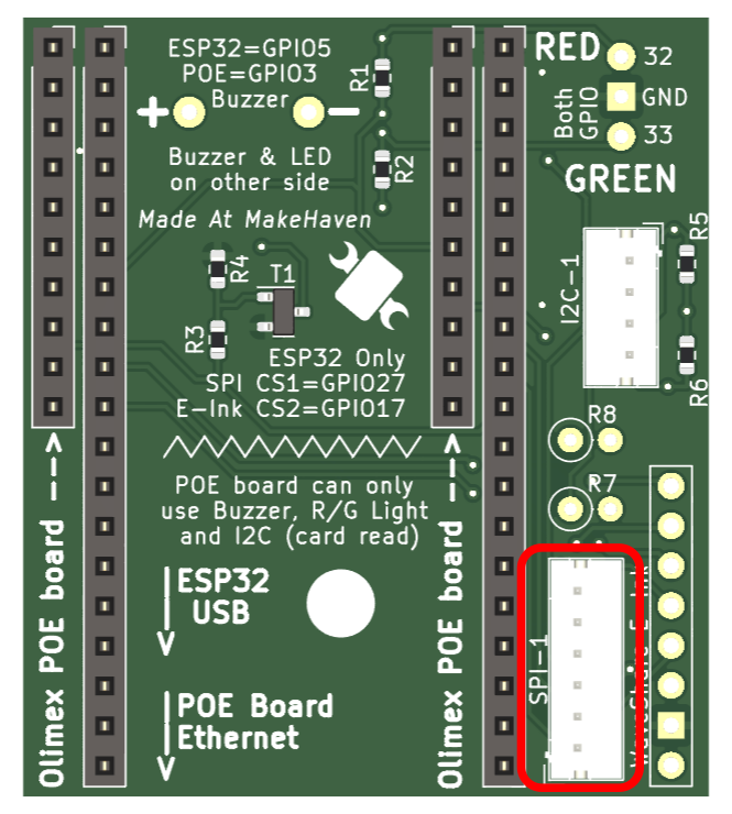
An SPI connector was added because it may be helpful for general use. There is no specific reason it is there, but perrhaps on will present itself...
ESPHome has good integration for Waveshare E-Paper displays. Here are the configuration options for using the E-Ink display. But be warned, you may want to read more about fonts in ESPHome before you start copy/paste-ing this willy nilly.
E-Paper Pin |
ESP Pin |
ESPHome Option |
|
|
N/A |
|
|
N/A |
|
GPIO 18 |
|
|
GPIO 19 |
|
|
GPIO 17 |
|
|
GPIO 16 |
|
|
GPIO 25 |
|
|
GPIO 26 |
|
Here is an example configuration for ESPHome, but you'll clearly want to change the messages...
# Example configuration entry
            font:
              - file: 'fonts/Comic Sans MS.ttf'
                id: font1
                size: 8

            spi:
              clk_pin: GPIO18
              mosi_pin: GPIO19

            display:
              - platform: waveshare_epaper
                cs_pin: GPIO17
                dc_pin: GPIO16
                busy_pin: GPIO25
                reset_pin: GPIO26
                model: 2.90in
                full_update_every: 30
                lambda: |-
                  it.print(0, 0, id(font1), "Hello World!");
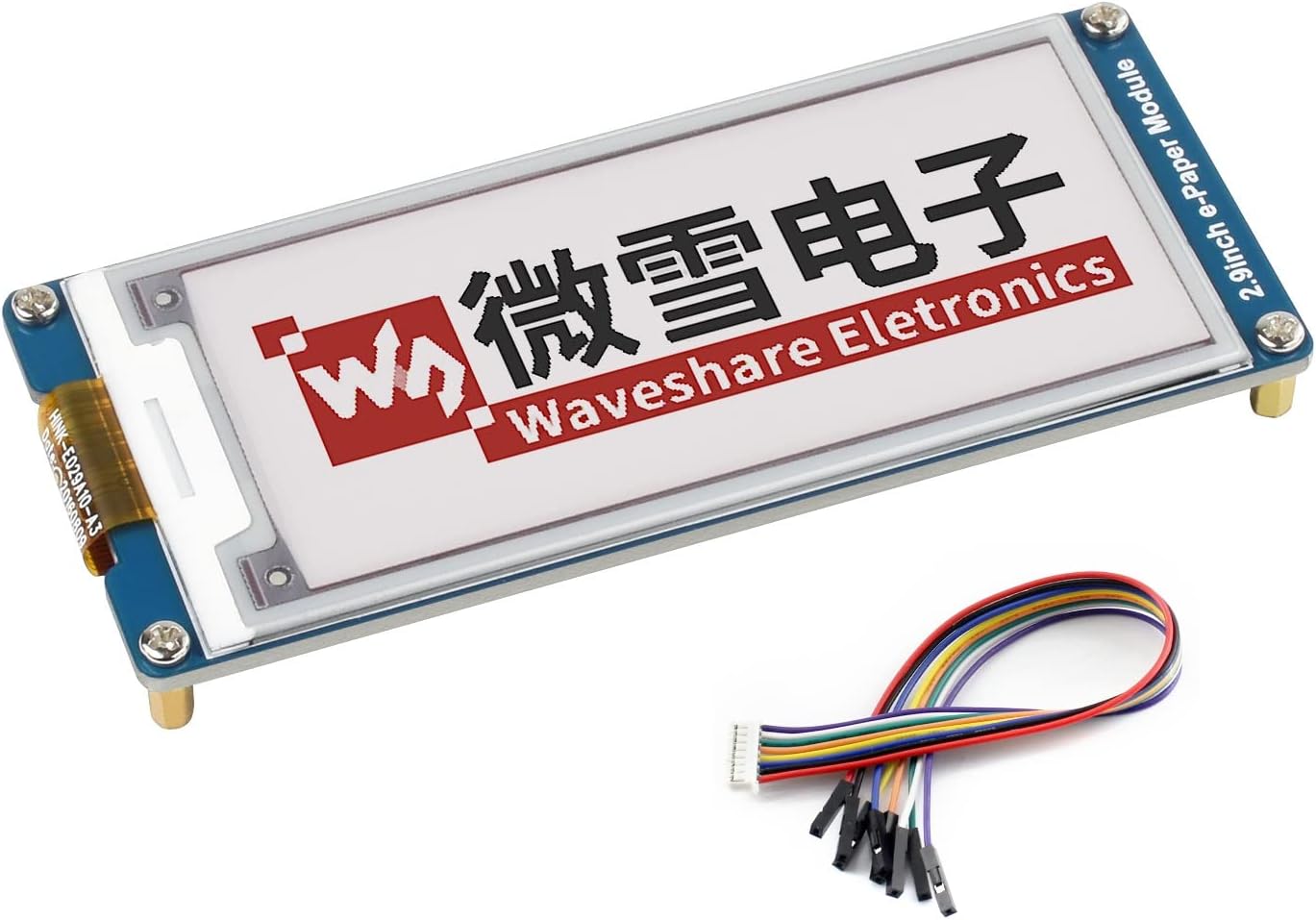
Finally, the pinout for the Waveshare is located here, and labeled on the back of the board for easier soldering of the often-included display connector cables. Here is an example of the waveshare boards, but they are available from many resellers, including Amazon.
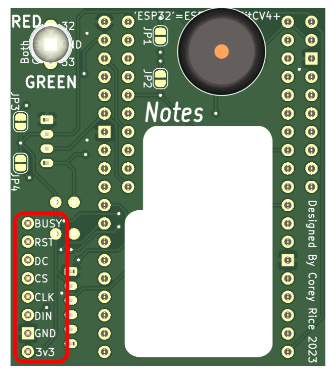
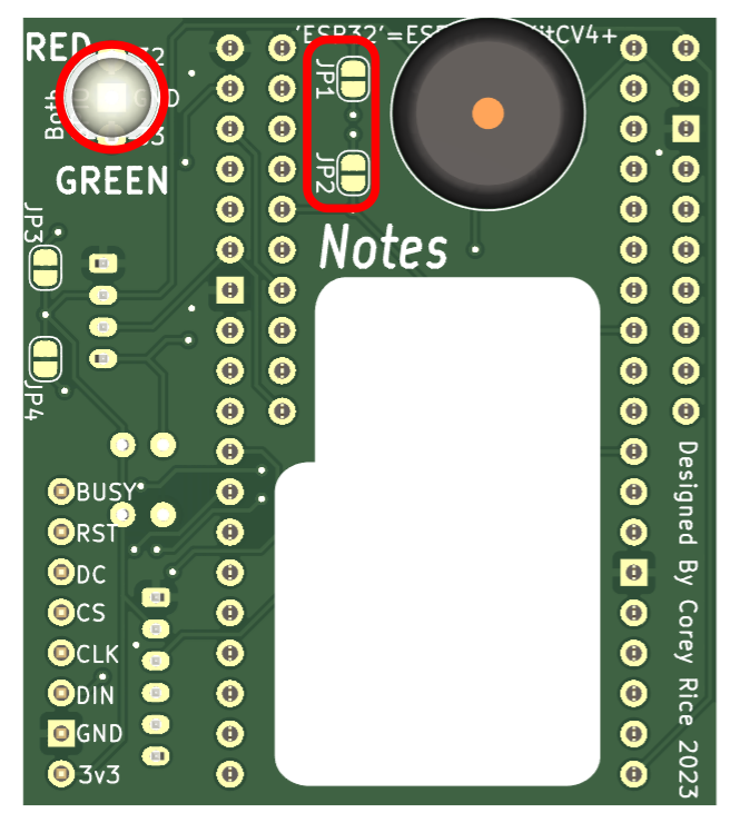
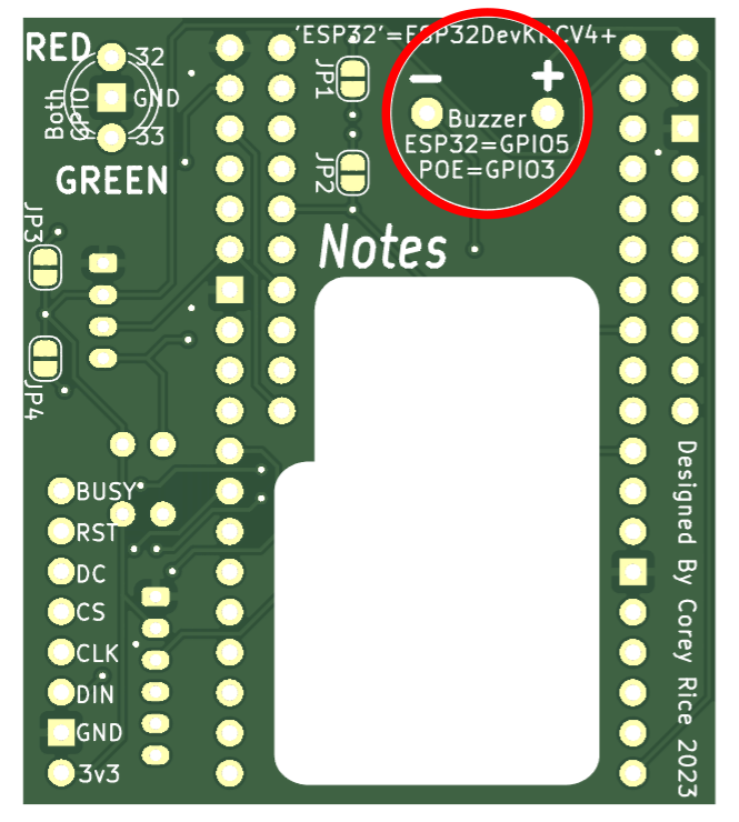
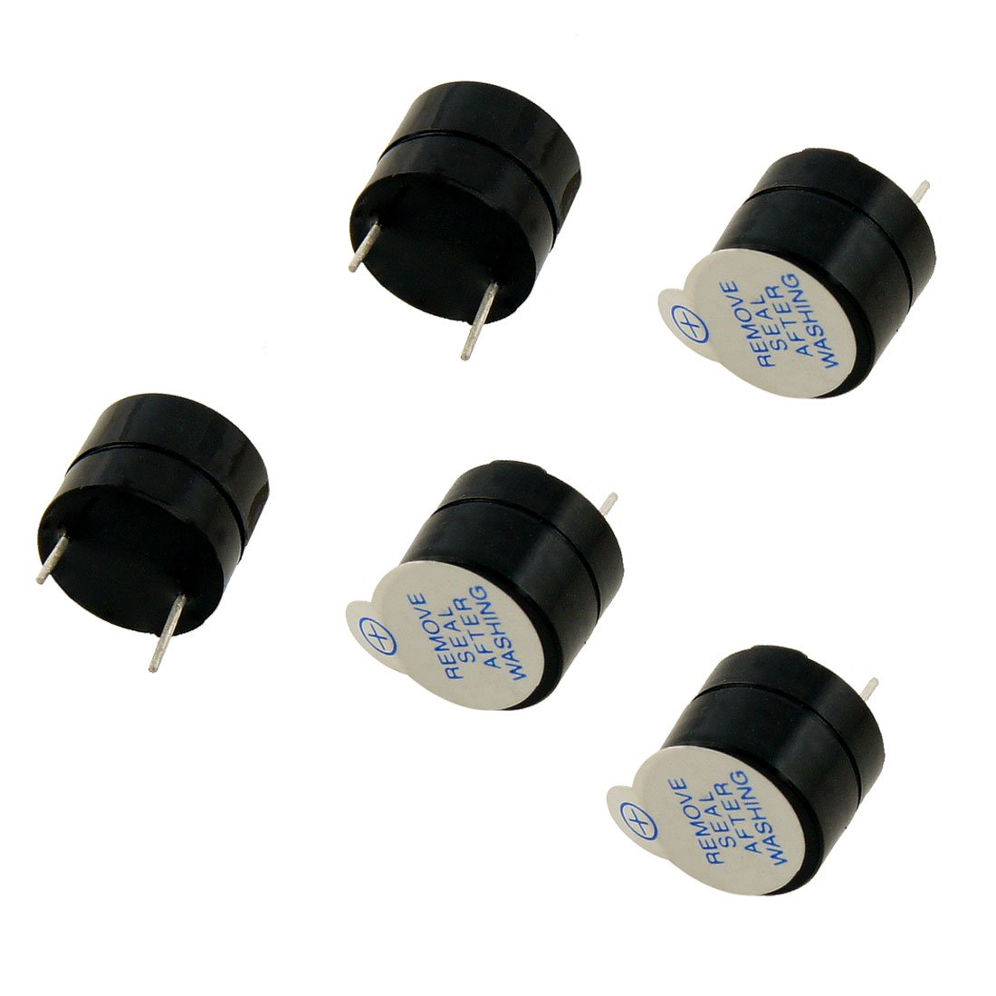
A little noise is great feedback. A 12mm buzzer such as this one can be soldered into place easily. The polarity and controlling pins have been silkscreened onto both sides of the board, to faciliate easier use with either choice of placement.
Often the Buzzer will be soldered directly onto the back of these boards - watch the polarity while soldering.
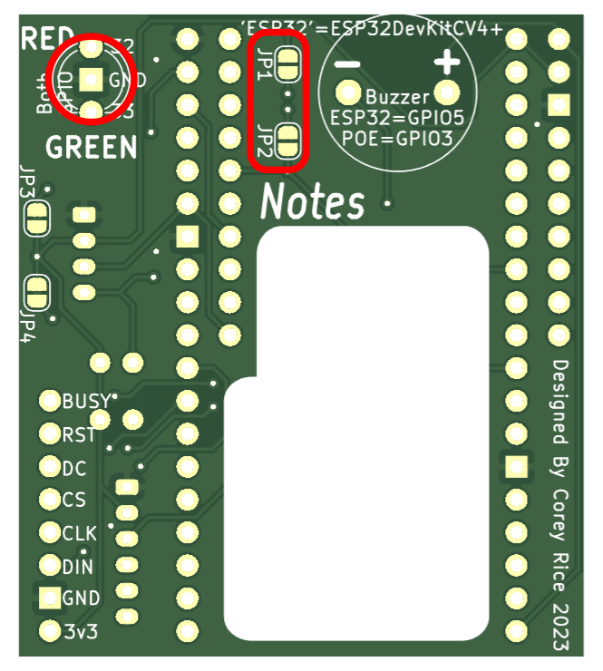
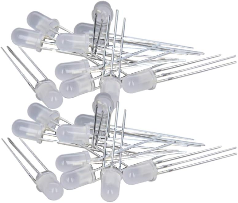
Indicator LEDs can provide great feedback to a used. Two-color LEDs like this may be an old-solution, but they do a great job as indicators without taking many pins. including a full RGB LEd is possible on this board, but avoided to stay inline with the paired tool-controller boards that can only fit this pinout.
Two 1k resistors are used to regulate current to the LEDs, but jumpers JP1 and JP2 are in parallel with these resistors. If resistors are wired inline with the LED off-board [presumably on panel-mount LED, connected by a few pigtails] you can solder bridge each jumper to short out the default 1k resistors. This will also allow you to configure the resistance values as you wish: just don't forget resistors for the LED.
The pin spacing here is perfect for one of the 5mm R/G LEDs on its own, or to solder in a small terminal block. Often the R/G LED will be soldered directly onto the back of these boards - watch the polarity while soldering.